

In our last post, Refrigeration Systems - Quench Control (Part 1), we discussed the industrial refrigeration process, and basic recycle temperature control. In what follows, we will discuss the limitations of traditional (basic) recycle temperature quench control and ways to improve this control.
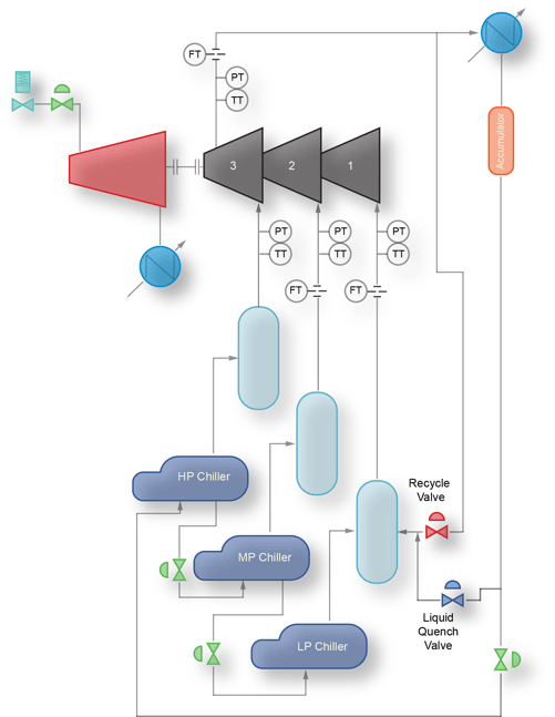
Figure 1 - Simplified Typical Refrigeration System Schematic
A quick review of the control challenge
Selecting an appropriate quench control temperature setpoint is the first hurdle. If the temperature setpoint is too low, an increase in the suction pressure can cause the setpoint of the temperature controller to be in the saturation zone or liquid zone of the refrigerant. If the temperature controller setpoint drops below the saturated vapor temperature at the current pressure, the controller will not be able to satisfy the setpoint, causing the control valve to integrate open. This excess liquid will create level problems in the suction drum and put unnecessary demands on the inventory of the refrigerant accumulator. Conversely, if the setpoint is set too high, the high suction temperature that results will tend to spoil the suction pressure or cause the compressor speed to increase to maintain the desired pressure.
Perhaps a bigger problem for the operator can be the interaction of the anti-surge controller and the temperature controller. The response of the temperature controller is much slower than the response of the anti-surge flow controller. This difference in responses causes the two controllers to be out of phase with each other. The common solution used by the operator is to put the temperature controller in manual to stop the swings. Once in manual, the temperature controller will not respond to an increase in recycle flow. Inadequate recycle cooling can quickly cause the compressor to take itself offline; the increase in recycle flow causes the suction temperature to increase, pushing the compressor closer to surge, which further increases the recycle demand.
Temperature Controller / Surge Controller interaction
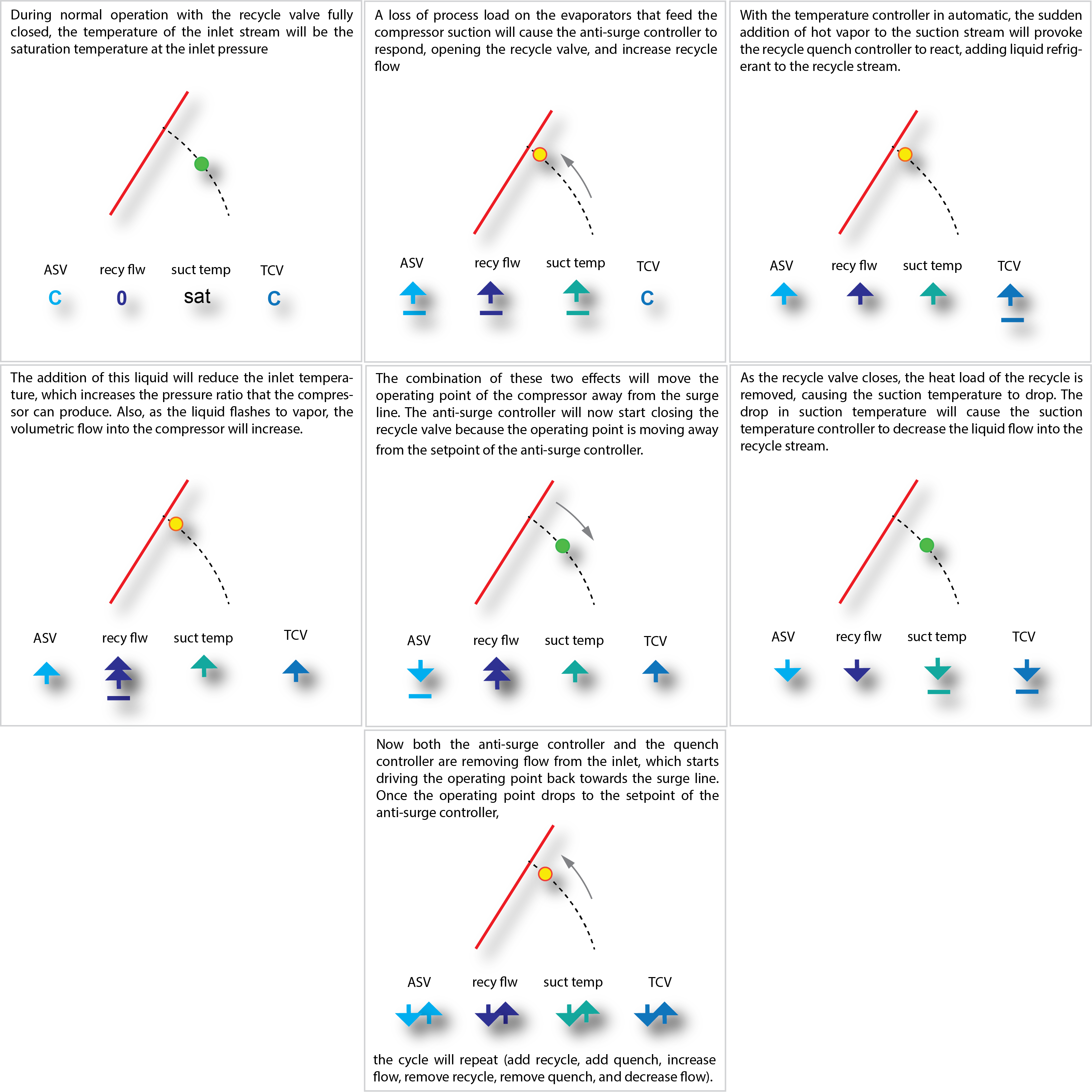
Figure 2 - Recycle/Quench control interaction
Traditional (Basic) “Fixed Setpoint” Temperature Control
Basic Temperature Control consists of a fixed temperature setpoint controller that regulates the quench flow based on the compressor suction or sidestream temperature. If the gas pressure remains within a narrow range, the controller provides adequate temperature regulation. However, as described earlier, process variations (upsets) that disturb the gas pressure often create problems for a “fixed” setpoint controller.
.png?width=662&name=Pressure%20Enthalpy%20Diagram%20Quench%20Post%201%20(VTDM).png)
Figure 3 - Pressure-Enthalpy diagram for typical refrigerant, with traditional fixed setpoint
The first improvement on the “fixed setpoint” controller is one where the temperature control setpoint is pressure compensated.
Pressure Compensated Temperature Controller Setpoint
Instead of using a fixed temperature for the controller setpoint, the equations of state of the refrigerant are used to calculate the saturation temperature at the gas pressure. The setpoint of the controller is then set to the saturation temperature at the current pressure plus an incremental amount of superheat (typically 5-10 deg C).
%20wCTCS.png?width=651&name=Pressure%20Enthalpy%20Diagram%20Quench%20Post%201%20(VTDM)%20wCTCS.png)
Figure 4 - Pressure-Enthalpy diagram for typical refrigerant, with pressure compensated setpoint
The pressure compensated temperature setpoint is an improvement on the fixed setpoint solution, but it doesn’t address the “out-of-phase” interaction of the surge controller and the temperature controller (illustrated in the Figure 2 "cartoon" above).
Enter the “coordinated recycle flow management” of the quench liquid.
Coordinated Recycle Flow Management
Coordinating the flow of the quench liquid with the flow of the recycle vapor allows proper control of the suction temperature without the flow swings that result from interactions between the anti-surge controller and the temperature controller. With a scheme that coordinates the liquid and vapor flows for recycle, the temperature controller becomes a trim adjustment to maintain a minimum superheat of the recycle stream rather than the primary control function of the temperature control valve.
The challenge for a coordinated control scheme is to manage the liquid flows for all operating conditions properly. One solution is to use a feed-forward function based on the relative mass flow rates through the two valves. If the operating pressures and densities of the fluids through the valves remain within a narrow range, this scheme will work fine.
The main drawback of this control scheme is that it requires a skilled technician to tune it properly in the field. Another shortcoming is its performance under off-design conditions. As the operating conditions deviate from the design conditions, the temperature management will be less precise, requiring more significant action by the temperature controller.
A more robust Coordinated Recycle Flow Management
A refinement of the feed-forward technique is to incorporate the fluid enthalpies and valve characteristics to allow proper quenching over a wide range of pressures and temperatures. A control system with the speed and capacity for advanced numerical methods is required, but many modern control systems now have this capability. Essentially, by calculating enthalpies, densities, and specific heats for the quench liquid and recycle vapor, a mass/energy balance can be implemented for determining the correct proportion of liquid and vapor to satisfy the minimum flow requirements of the compressor. If the compressor control system does not have these math or programming features, it is sometimes possible to perform the advanced operations (equations of state calculations) in a separate computer or co-processor.
Getting it done.
Fundamentally, we need to calculate the amount of energy in the recycle stream that must be removed to cool the recycle stream to the desired temperature.
The coordination algorithm calculates the specific heat, density, and saturation temperature of the recycle stream at the stream temperature and pressure. The specific heat of the recycle gas multiplied by the desired temperature reduction provides the specific energy value that must be removed by quenching. The mass flow of the recycle streams is calculated using the anti-surge valve Cv, differential pressure, and the density of the hot gas at the inlet of the valve.
Now that we know the mass flow through the anti-surge valve and heat per mass unit to be removed, the total energy that must be removed from the gas can be calculated.
The coordination algorithm needs to calculate the enthalpy of the liquid entering the quench valve. By calculating the saturation enthalpies downstream of the valve (compressor suction pressure), the liquid fraction in the outlet stream of the quench valve can be calculated. Using the enthalpy of evaporation, liquid fraction, and heat removed from the hot vapor, the required mass flow of liquid is calculated. The quench valve Cv, and characteristic, along with a density calculation for the quench stream, as well as the pressure entering the quench valve provide the final information needed to determine the required opening of the quench valve.
Small Tweaks
Once the liquid and vapor recycle flows are coordinated, the gains of these valves can be used to adjust the gain of the anti-surge controller, further improving the stability of the controls. When both valves are being used for meeting the minimum flow requirements, a lower gain is used for the anti-surge PID controller than is required when only the vapor valve is being used.
Liquid injection into the recycle vapor stream is not always needed. At low recycle flows, the heating contributed by the hot recycle gas is not enough to upset the suction temperature since the hot gas is mixing with a much larger cold stream from the evaporators. Since the quench stream is injected into the recycle gas line, at low recycle flows (low gas velocities), the mixing of the liquid and gas is poor, resulting in liquid carry-over into the drum. The coordinated scheme delays the addition of quench liquid until there is enough recycle gas flow to support the proper evaporation of the quench liquid.
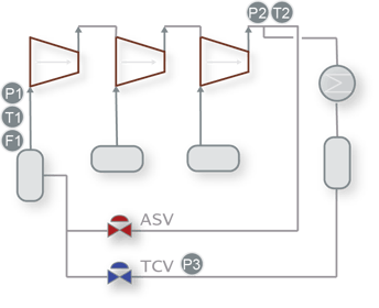
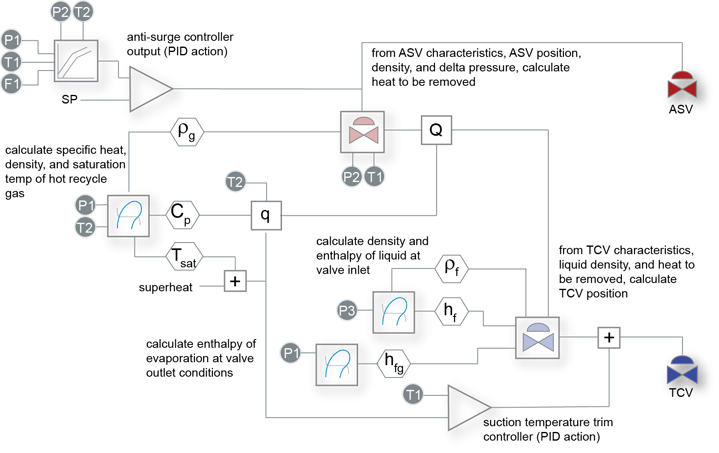
Figure 5/6 - With the instrumentation normally available in an anti-surge control system, the thermodynamic properties of the recycle gas and quench liquid can be calculated. These properties are used to coordinate the movement of the temperature control valve during action of the anti-surge valve.