

We're going to change it up a little this post with a guest blogger, Mr. Harry Cheddie, P.Eng. CRE, CQE, CFSE; an industry-recognized expert in industrial safety.
In what follows, Harry provides an overview of the typical redundant hydraulic trip schema and then calculates and compares their respective reliability and spurious (nuisance) trip rates.
It's important to note that to keep the complexity at an absolute minimum, we are only going to concern ourselves with the fundamental "architecture" of the solutions (we assume that the components making up the different systems are identical - as far as possible.)
Different "trip" interface configurations have been promoted, and are presently being used, for turbine shutdown and protection (typically discussed within the framework of turbine overspeed.)
We'll begin our discussion by talking about the simple "pluses" (+) and "minuses" (−) of four (arguably three) of the most common redundant configurations.
* a quick note: for all of the configurations discussed, we are assuming a "de-energize to trip" configuration. That is, power is removed from the trip solenoid upon detection of a trip/shutdown condition.
And, we're not going to discuss the online repair-ability / online test-ability of the architectures here; we'll address those issues in a follow-up post.
Redundant Configuration #1. "Serial" - Single two-out-of-two (2oo2) voting
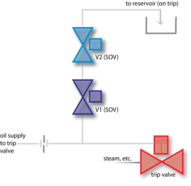
With the single 2oo2 schema, both solenoids and associated valves have to function normally for a "trip" to occur.
The single 2oo2 hydraulic trip system consists of two solenoid-operated-valves (SOVs) in series activating the main trip valve for the turbine by porting hydraulic fluid to drain.
During normal operation, if either SOV is closed, the full supply pressure of the control oil is applied to the trip valve actuator.
A trip will occur (trip valve closes) when both SOVs open, causing the trip header to drain faster than the control oil supply can refill the header.
(+) On the plus side, this arrangement limits the potential of a spurious trip if one SOV fails open.
(−) On the minus side, either SOV can fail closed, which causes a total loss of the safety function (reliability). The single 2oo2 schema is not recognized as a valid hydraulic trip architecture by the American Petroleum Institute (API.)
Redundant Configuration #2. Parallel, One-out-of-two (1oo2) voting.
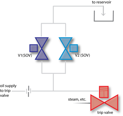
With the 1oo2 schema, only one solenoid and associated valve have to function normally for a trip to occur.
The 1oo2 hydraulic trip system consists of two parallel SOVs, with either of them activating the main trip valve for the turbine by porting hydraulic fluid to drain.
During normal operation, both SOVs are closed, causing the full supply pressure of the control oil to be applied to the trip valve actuator.
A trip will occur (trip valve closes) when either SOV opens, causing the trip header to drain faster than the control oil supply can refill the header.
(+) On the plus side this configuration minimizes the risk of a total loss of the safety function by providing a parallel "redundant" trip path, and is recognized as a valid interface by API.
(−) On the minus side, if a single valve should fail open, the turbine will experience a spurious trip.
Redundant Configuration #3. Two-out-of-three (2oo3) voting
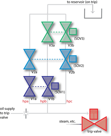
With the 2oo3 schema shown above, two of the solenoids and two of the associated valves (in the same hydraulic path [hpx]) have to function normally for a successful trip.
The 2oo3 hydraulic trip system consists of three sets of solenoid and valve assemblies (2 valves and 1 solenoid per set) porting hydraulic fluid to drain and activating the main trip valve for the turbine.
During normal operation, all valves are closed, causing the full supply pressure of the control oil to be applied to the trip valve actuator.
A trip will occur (trip valve closes) when two of the three valve sets operate, causing the trip header to drain faster than the control oil supply can refill the header.
(+) Big plus side here. Unlike the previous configurations, failure of a single valve will not result in a spurious trip, and will not result in a loss of the safety function. API recognizes the 2oo3 schema as a valid trip interface configuration.
(−) Nothing obvious, aside from complexity (perceived or otherwise).
Redundant Configuration #4. Dual, two-out-of-two 2oo2(2) voting
%20voting.png?width=373&name=2oo2(2)%20voting.png)
The 2oo2(2) schema combines both the serial and parallel configurations (configurations one and two above). Two solenoids and their associated valves in the same hydraulic path (hpx) have to function normally for a successful trip.
This hydraulic trip system consists of two parallel sets of SOVs (two valves in series per set) activating the main trip valve for the turbine by porting hydraulic fluid to drain.
During normal operation, all four SOVs are closed, causing the full supply pressure of the control oil to be applied to the trip valve actuator.
A trip will occur (trip valve closes) when both SOVs in at least one parallel-set opens, causing the trip header to drain faster than the control oil supply can refill the header.
(+) Same big plus as the 2oo3 configuration above; failure of a single valve will not result in a spurious trip and will not result in a loss of the safety function. API also recognizes the 2oo22 schema as a valid trip interface configuration.
(−) Nothing obvious, maybe there's a perception that having four solenoids and four valves adds complexity (compared to the 2oo3), but let's continue and come back to this.
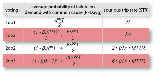
Trip Interface Architecture availability and reliability: 1oo2 vs 2oo2 vs 2oo3 vs (2oo2)2
So which solution is better (from a reliability and spurious trip rate perspective), and more importantly; how much better is one solution over the other?
To answer that question we are going to compare the redundant schema using two of the most common and "easily understood safety metrics;" the average probability of failure on demand (PFDavg) and the spurious trip rate (STR).
Abbreviations:
-
- PFDavg = average probability of failure of a system
- STR = spurious or nuisance trip rate
- λDU = dangerous undetected failure rate (of solenoid and valve(s))
- λD = dangerous failure rate (of solenoid and valve(s))
- λS = safe fail rate (of solenoid and valve(s))
- T = proof test interval (time)
- β = common cause failure
- RRF = risk reduction factor
- MTTR = mean time to repair
- MTTF = mean time to failure
Assumptions and Equations:
The following simplified equations will be used as a basis for the following calculations. Additionally, these equations are based on the following assumptions:
-
- MTTR is very small as compared to the proof test interval for all architectures, and is not factored into the
PFDavg equations* (but MTTR is used in the spurious trip rate calculations) - MTTR is assumed to be the same for each architecture**
- Testing is 100% efficient
- All dangerous failures are undetected i.e. λD = λDU (there are no λDD failures)
- All architectures use the same solenoids and solenoid operated valves (same λDU and same λS)
- λDU {1/h] = 1.15E-06
- β = 0.025
- T [h] = 8760
- λS [1/h] = 2.50E-06
- MTTR is very small as compared to the proof test interval for all architectures, and is not factored into the
* it's acknowledged that assuming MTTR is not significant is probably going to be controversial to some. And, we also want to acknowledge that while the MTTR may be statistically insignificant, just a few hours of downtime can be very significant to many critical applications.
** This is controversial too. It's understood that the "repair-abilities" of the different architectures create different MTTRs, but for the sake of simplicity, we are assuming that the repair-ability for each voting schema is the same. In a follow-up post we'll address the different repair-ability limitations of the different architectures.
Equations:
Derivation of equations for single 2oo2
The single 2oo2 system will fail if:
- V1 OR V2 fails closed
.png?width=469&name=2oo2%20fail%20closed%20(dark%20gray).png)
PFDavg = (1-β)λDUT + (βλDUT/2) = 9.95E-03
RRF = 101 (with one year test interval)
For the single 2oo2 system, a nuisance or spurious trip will occur if:
- V1 AND V2 fails open
.png?width=196&name=2oo2%20fail%20open%20(dark%20gray).png)
STR = 2(λS)2MTTR = 2.10E-09
MTTFspurious (in years) = 54360
Derivation of equations for "parallel" 1oo2
The parallel 1oo2 system will fail if:
- V1 AND V2 fails closed
.png?width=213&name=1oo2%20fail%20closed%20(dark%20gray).png)
PFDavg = ((1-β)λDUT)2)/3) + (βλDUT/2) = 1.58E-04
RRF = 6325 (with one year test interval)
For the 1oo2 system, a nuisance or spurious trip will occur if:
V1 OR V2 fails open
.png?width=454&name=1oo2%20fail%20open%20(dark%20gray).png)
STR = 2(λs) = 5.00E-06
MTTFspurious (in years) = 23
Derivation of equations for 2oo3
The 2oo3 system will fail if:
V1 AND V2 fails closed, OR V1 AND V3 fails closed, OR V2 AND V3 fails closed
.png?width=657&name=2oo3%20fail%20closed%20(dark%20gray).png)
‡ which is the same as three 1oo2 systems.
PFDavg = [3(((1-β)λDU)2T)2)/3] + [6(βλDUT/2)] = 8.52E-04RRF = 1174 (with one year test interval)
‡ Factor of six (instead of three as shown in equation table) is used above because there are two valves per set - which increases "β"
For the 2oo3 system, nuisance or spurious trip will occur if:
V1 AND V2 fails open, OR V1 AND V3 fails open OR V2 AND V3 fails open.png?width=680&name=2oo3%20fail%20open%20(dark%20gray).png)
‡ which is the same as three 2oo2 systems.
STR = 3(2(λS)2MTTR = 6.30E-09
MTTFspurious (in years) = 18120
Derivation of equations for 2oo2(2)
The 2oo2(2) system will fail if:
V1 AND V2 fail closed OR, V1 AND V4 fail closed OR,
V3 AND V2 fail closed OR, V3 AND V4 fail closed
%20fail%20closed%20(dark%20gray).png?width=503&name=2oo2(2)%20fail%20closed%20(dark%20gray).png)
‡ which is the same as four 1oo2 systems.
PFDavg = [4(((1-β)λDUT)2)/3] + [4(βλDUT/2)] = 6.32E-04RRF = 1581 (with one year test interval)
For the 2oo2(2) system, A nuisance or spurious trip will occur if:
V1 AND V3 fails open OR, V2 AND V4 fails open
%20fail%20open%20(dark%20gray)%20r1.png?width=461&name=2oo2(2)%20fail%20open%20(dark%20gray)%20r1.png)
‡ which is the same as two 2oo2 systems.
STR = 2*2(λS)2MTTR = 4.20E-09
MTTFspurious (in years) = 27180
Voting Architecture Summary Table:
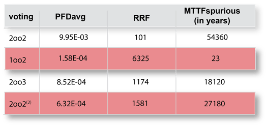
To summarize; the 1oo2 architecture offers a very compelling RRF at the expense of an almost guaranteed nuisance trip (especially if there's a couple of systems with this architecture). The single 2oo2 architecture offers the best defense against nuisance trips, at the expense of a comparatively low RRF (pretty high risk of a dangerous failure, especially if there's a couple of systems with this architecture.)
From PFDavg, and STR perspectives, of the architectures we have looked at, the best compromise between the 1oo2 and the 2oo2 voting schema - that maximizes reliability and availability - is the 2oo2(2) architecture.
And that's about it for this post.
If you'd like to take a look at Harry's books, here's a link to a list on Amazon: Harry's books
If you'd like to learn more about Harry or Cteris, here's a link to their website: https://cteris.com/
As always, your "likes," comments, and questions are appreciated.
Thanks for your interest, see you next time!