

Proper selection of the recycle valves for a refrigeration compressor can be significantly more complicated than the selection valves for most other anti-surge applications. Refrigeration Compressors that have a liquid quench stream for recycle cooling present significant complications for the selection of the recycle valves. The design of the liquid quench system is important for ensuring stable operation of the compressor when the process loads are low.
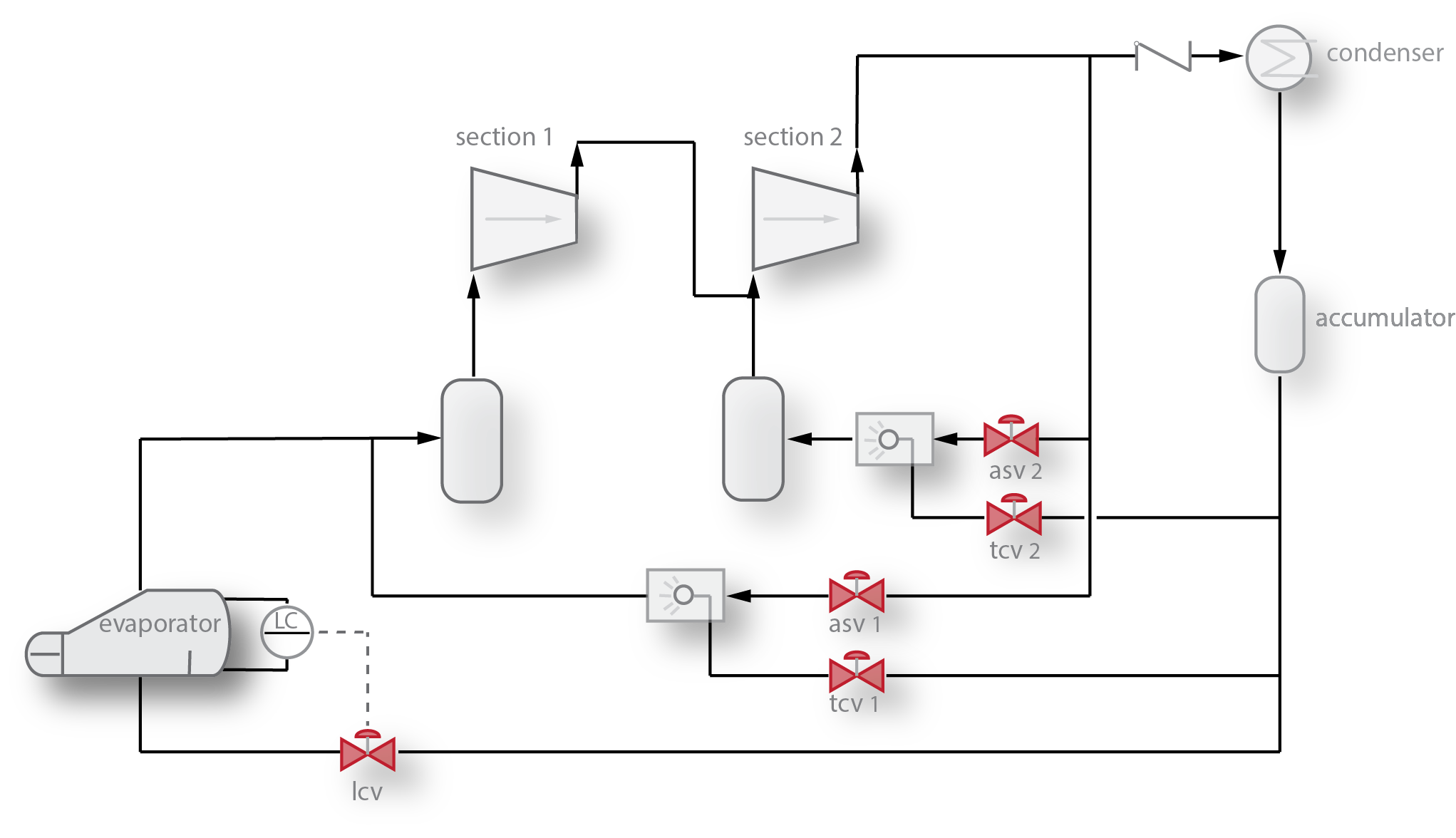
Figure 1: Two stage refrigeration compressor with liquid quench recycle temperature control. If the heat load into the Evaporator stops, the vapor flow to from the evaporator to the suction drum stops, causing the suction pressure to drop (and the pressure ratio to increase). Increasing the pressure ratio drives the compressor operating point towards surge.
Background
When a compressor approaches the surge limit, the anti-surge system must react to prevent the operating point from moving any closer to the limit. A compressor produces a flow rate based on the inlet density and the pressure ratio across the compressor. The suction flow results from the differential pressure ratio and the compressor characteristic curve. If the inlet density changes, the characteristic curve changes. A change of the suction and/or discharge pressure results in a change of the pressure ratio. It is a common misconception that the flow is the fundamental parameter that the anti-surge controller is managing to prevent the operating point from dropping below the surge limit line. Actually, the anti-surge system prevents surge by changing the pressure ratio and sometimes the inlet density. The suction flow produced by a centrifugal compressor is a result of the differential head across the compressor. The pressure ratio and gas density at the suction determines the differential head imposed on the compressor.
The following equations show parameters that affect the differential head:

P2: Discharge Pressure
P1: Inlet Pressure
s: Polytropic Exponent
Z: Compressibililty (deviation from ideal gas)
R: Ideal gas constant
T1: Inlet Temperature
MW: Molecular weight
Equation 3 shows that a change in the density will have an inverse affect on the differential head. However, if the density change is solely due to a change in the pressure, the head will not change due to the density change. In this case, the head change will be due to the change in the pressure ratio.
In the case of a refrigeration compressor, the operating point moves towards the surge limit when the heat load on the evaporator that feeds the compressor drops off. When the evaporator heat load drops, the vapor produced by the evaporator drops, causing the compressor inlet pressure to drop. Since the final discharge pressure of the compressor is primarily a function of the condenser temperature (due to the cooling medium temperature), the discharge pressure is fairly constant. Therefore, as the inlet pressure drops, the pressure ratio increases since the discharge pressure is constant.
When the operating point approaches the surge limit, the anti-surge controller will start opening the recycle valve. The gas that is recycled will replace the vapor that is no longer coming from the evaporator. The addition of this vapor will stop the pressure ratio from dropping further. But, since the temperature of the recycle gas is not cold, the density of the inlet gas will be lower, which causes the differential head across the compressor to increase. This increase in head will push the operating point towards the surge limit, leading to a further increase in the output of the anti-surge controller. For low recycle flows (when there is still a significant amount of cold vapor coming from the evaporator), no cooling is required for the anti-surge recycle flow. But as the recycle flow increases, there is a point where the increase in temperature of the inlet will no longer be balanced by the cold vapor.
This will cause the recycle valve to open fully as the differential head increases. At this point, the suction pressure will rise, the discharge temperature will rise, a pressure controller on the suction will start venting gas to the flare and the compressor discharge temperature will become dangerously high.
When a refrigeration compressor is in full recycle, the amount of cooling liquid that must be added to the recycle stream to prevent a significant rise in the inlet temperature is substantial. Depending on the refrigerant and the pressure ratio across the compressor, the liquid flow during full recycle (no vapor contribution from the evaporator) can be as much as 40% of the total mass flow to the compressor.
Valve Selections
Vapor Recycle
For refrigeration compressors, there are two operating scenarios that have the most significant effect on the sizing of the vapor recycle valve; startup and trip. In general, if the valve is adequate for these two operating condition, it will be large enough for any other conditions.
Startup
The normal procedure for starting a refrigeration compressor is to fully open the recycle valve prior to accelerating the compressor to the normal operating speed. Typically, the operator does not add the quench liquid until the compressor is at full speed. Without recycle cooling, the pressure ratio across the compressor will be much lower than normal but the high suction temperature will cause the differential head to be high. To meet the flow requirements of the compressor during this startup scenario, a large recycle valve is required due to the lower than normal differential pressure across the valve. If the vapor recycle valve is sized based on the assumption that the inlet temperature remains low during startup, the compressor will usually experience surging during the acceleration of the compressor, even though the vapor recycle valve is fully open.
Driver trip
A driver trip is typically the scenario that has the most significant influence on the sizing of the recycle valve. When the driver trips, the speed of the compressor will drop quickly, reducing the head that the compressor can produce. At the same time, the differential head across the compressor does not drop nearly as quickly because of the volumes of gas in the inlet vessels and piping and the piping volume at the discharge. Within a couple of seconds after tripping, the speed will drop enough to push the operating point into the surge limit. Since the speed is dropping, the differential pressure that the compressor can produce is also dropping. This limits the differential pressure available to the recycle valve.
It is a common for the plant operators to prohibit the use of the liquid quench during a trip in order to avoid the risk of liquid carry-over into the compressor. Without any liquid contribution to the recycle, the entire flow required by the compressor to avoid surge must be provided by the vapor recycle valve.
Additionally, without cooling, the amount of vapor required to prevent surge is significantly increased due to the effect of inlet temperature on the differential head.
Actuation
Accurate and fast valve positioning is important for any anti-surge valve application. Generally, a valve that strokes from closed to fully open in less than two seconds will be adequate. An accurate positioner with a volume positioner should be included with the actuator. Minimal hysteresis is important for preventing control instabilties.
Liquid Recycle (quench)
The liquid that is added to the recycle vapor stream for cooling is a significant contributor to the prevention of surge. The mass flow contribution by the liquid recycle can be as much as 40% of the total recycle flow. While the flow from the vapor recycle has a more significant impact on reducing the pressure ratio across the compressor, the liquid recycle (due to the cooling) has a more significant impact on limiting the differential head imposed on the compressor. Without adequate liquid flow into the recycle stream, the prevention of surge and ultimately, the stability of the process can be difficult to ensure.
There are several problems with the operation of the liquid recycle that cause operators to distrust the temperature controller and limit its use. These problems are primarily associated with the management of suction drum levels.
Drum Level Problems
The first section suction drum is normally operated with no liquid (dry). Since the normal suction pressure on refrigeration compressors is low, it is difficult to remove any liquid that might accumulate in the drum. At low pressure, it is difficult to pump the refrigerant out because the liquid will tend to flash in the suction of the pump. If there is excessive liquid flow for the quench or the liquid does not fully flash, liquid will begin to accumulate in the drum.
Valve Selection Problems
Sizing the quench valve is not difficult. Essentially, the enthalpy contributed by the hot recycle gas must be removed by the flashing of the quench liquid. This will define the mass flow requirements for the valve. The differential pressure is set by the suction and discharge pressures and the pressure drop across the spray nozzle. Selecting the correct valve is more difficult. Since the pressure of the liquid that enters the valve is only slightly higher than the saturation pressure of the liquid, flashing across the valve will be inevitable. Cavitation will be very difficult to avoid.
It is common for the quench valve to eventually develop leakage problems due to cavitation damage of the seat and plug. Leakage will eventually cause a liquid level to develop in the suction drum. When the leakage becomes signficant, the operator will block-in the quench valve to prevent the drum level problem. Now, if an upset occurs in the process that requires significant recycle, the operator must un-block the liquid valve as quickly as possible to prevent the compressor from taking itself offline and tripping.
To prevent cavitation damage to the liquid valve, special attention should be paid to the design and selection of the spray nozzle as well as the valve selection. If a spray nozzle is incorporated into the design that can maintain a constant pressure drop, regardless of flow, the cavitation in the valve can be minimized. If most of the pressure drop can be taken across the spray nozzle, the cavitation coefficient of the valve will be increased. Using a spray nozzle with a constant pressure drop will ensure that even at low flows, the valve is not subjected to excessive flashing and cavitation. The valve will be much larger due to this lower differential pressure across the valve, but the valve will last a lot longer.
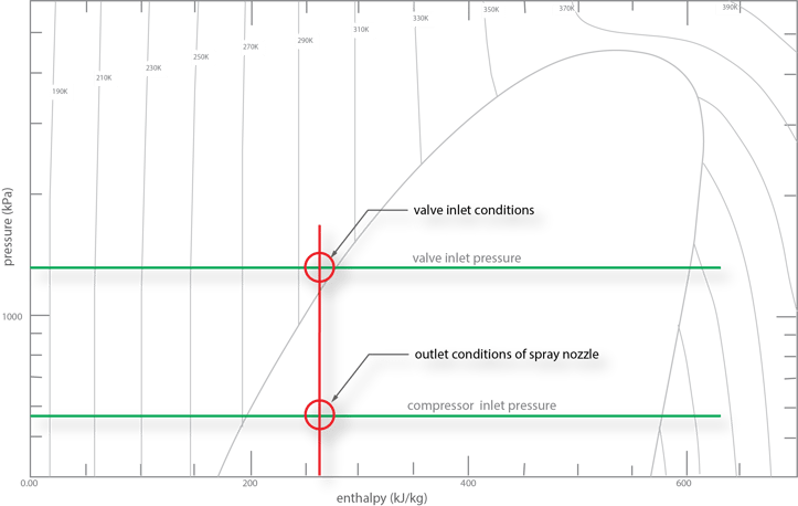
Figure 2: The liquid that enters the temperature control valve is only slightly subcooled. With only a small drop in the pressure of the liquid, flashing will begin to occur. If the majority of the pressure drop can be performed by the liquid spray nozzle, the cavitation damage to the valve can be minimized
Actuator
As with the vapor recycle valve, the liquid valve actuator should include an accurate positioner with a volume booster. Low hysteresis is important for this valve. If the valve cannot smoothly manage the cooling liquid flow, swings will result in the operating point. Eventually, the operator will put the temperature controller in manual to stop the swings. Unlike the vapor valve, there is no need for fast actuation in this service.
Spray Nozzle Selection
The spray nozzle selection can be the most important function to ensure a successful anti-surge installation. If the nozzle is not selected correctly, the performance of the quench system will be inadequate, especially at low flows. If the spray nozzle is ineffective at atomizing the quench liquid, the contact with the hot vapor will be inadequate. Inadequate contact will mean insufficient cooling and incomplete evaporation of the liquid. The result will be poor cooling and an accumulation of liquid in the suction drum. And ultimately, the operators will lose confidence in the quench system.
There are companies such as IMI-CCI that have experience producing attemperators for steam systems that can also be used for quench service in refrigeration systems. These devices integrate the valve, actuator and spray nozzle into a single assembly. The valve is designed to tolerate the phase change that is inevitable with high vapor pressure liquids and the nozzle is designed to atomize the liquid over a large flow range.
Special Control Algorithms
Tri-Sen has developed special control algorithms that manage the liquid flow based on the anti-surge recycle flow demand rather than just for temperature control. The algorithm uses the thermodynamic properties of the gas to calculate the amount of liquid required to remove the heat of compression from the recycle stream. A temperature controller is still used, but just for trimming the liquid flow to prevent over-quenching. These algorithms can only be effective, however, if the temperature control valves and spray nozzles are properly selected and maintained.